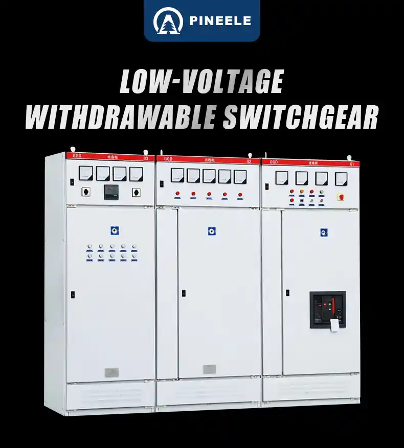
The GGD Type Low Voltage Fixed Switchgear is a versatile, safe, and robust electrical cabinet system engineered for three-phase AC 50/60Hz power distribution guide networks. With a maximum operating voltage of AC 690V and a rated current of up to 3150A, this fixed-type low-voltage switchgear is a trusted solution across industries. It is widely deployed in power plants, substations, industrial facilities, and mining enterprises to manage lighting control, power distribution, motor starting, and reactive power compensation.
Compliant with IEC 60439-1 standards, the GGD Type Low Voltage Fixed Switchgear ensures high breaking capacity, reliable performance, excellent thermal stability, and flexible configurations to meet the demands of complex low-voltage systems.
Applications of GGD Type Low Voltage Fixed Switchgear
- Urban power distribution networks
- Petrochemical and energy systems
- Industrial automation plants
- Substations and transformer rooms
- Renewable energy control panels
- Commercial building electrical rooms
Structural Features of GGD Type Low Voltage Fixed Switchgear
- Frame: Constructed with an 8MF or C-type cold-rolled steel frame using modular welding for superior strength and precision.
- Ventilation: Features upper and lower ventilation slots for natural heat dissipation, ensuring optimal temperature control.
- Compartments: Separate sections for busbars, functional units, and cable terminals to minimize fault propagation.
- Protection: Rated up to IP41, providing excellent dust protection and operator safety.
- Finish: All metal parts are galvanized and powder-coated with orange-textured polyester for corrosion resistance and durability.
- Doors: Equipped with compression-resistant rubber seals and removable hinges for easy maintenance.
Technical Specifications of GGD Type Low Voltage Fixed Switchgear
| Model | Rated Voltage (V) | Rated Current (A) | Short-Circuit Breaking (kA) | 1s Short-Time Withstand (kA) | Peak Withstand Current (kA) |
|---|
| GGD1 | 400 / 690 | A: 1000 / B: 600 / C: 400 | 15 | 15 | 30 |
| GGD2 | 400 / 690 | A: 1600 / B: 1000 / C: 600 | 30 | 30 | 63 |
| GGD3 | 400 / 690 | A: 3150 / B: 2500 / C: 2000 | 50 | 50 | 105 |
Main Circuit Schemes & Busbar Configurations
- Schemes: Offers 129 main circuit schemes with over 298 specifications for tailored solutions.
- Layouts: Customizable for motor control, power distribution, and capacitor banks.
- Busbars: Available in aluminum or copper, based on rated current and user needs.
- Connections: Uses tin soldering and pressed surfaces for low resistance and reliable contact.
- Options: Flexible mounting configurations, including single-row aluminum or double-row copper busbars.
Component Selection & Auxiliary Circuits
- Components: Incorporates high-quality options like DZ20, BRM1, HD13BX, HS13BX, and LMZ3D current transformers.
- Auxiliary Circuits: Divided into power supply and relay protection schemes.
- Space: Ample room for secondary control relays, meters, and PLC modules.
- Control Voltage: Supports customization, including AC380V/220V and DC110V/220V.
Dimensions & Installation
| Cabinet Type | Width (mm) | Depth (mm) | Installation Height (mm) |
|---|
| Power / Bus Cabinet | 600 / 800 / 1000 / 1200 | 800 / 1000 | Customizable |
| Feeder Cabinet | 600 / 800 | 800 / 1000 | Customizable |
| Motor Control | 600 / 800 | 800 / 1000 | Customizable |
| Reactive Power | 600–1000 | 800 / 1000 | Up to 1800 mm |
Working Conditions
| Parameter | Specification |
|---|
| Ambient Temperature | -30°C to +50°C (avg. ≤ +35°C) |
| Max Altitude | ≤ 2500m |
| Relative Humidity | ≤50% at +40°C; ≤90% at +20°C |
| Installation Inclination | ≤5° |
| Site Conditions | No flammable gas, corrosion, or shock |
| Storage Temperature | -25°C to +55°C (max 70°C short-term) |
Installation & Commissioning
- Setup: Follow factory-supplied installation drawings.
- Mounting: Secure to foundation with bolts and level on steel channels.
- Busbars: Clean, grease, and tighten all connections.
- Inspections:
- Verify electrical contacts and mechanical interlocks.
- Confirm relay and fuse settings align with design.
- Test insulation resistance (≥ 11MΩ with 690V megger).
- Ensure auxiliary circuits match the schematic diagram.
Supplied Documents
- Product instruction manual
- Test reports and certifications
- Electrical diagrams and installation layouts
- Spare parts list and packing list
- Operation handle, door keys, and wiring guide
Frequently Asked Questions (FAQ)
Q1: What’s the difference between GGD1, GGD2, and GGD3?
A: The models vary in rated current and short-circuit capacity. GGD3 offers the highest performance, supporting up to 3150A and 105kA peak withstand current.
Q2: Can GGD Type low voltage Fixed Switchgear be used outdoors?
A: No, it’s designed for indoor use. For outdoor applications, consider weatherproof enclosures or alternatives like GCK or GCS switchgear.
Q3: Does it support reactive power compensation?
A: Yes, it integrates with GGJ1 and GGJ2 capacitor compensation cabinets for effective reactive power management.
Q4: Can I replace aluminum busbars with copper?
A: Yes, copper busbars are available for enhanced conductivity and reduced thermal expansion, based on your specifications.